|
|
| Name: | DIA25.4mm Berek Compensator Plate CA11mm/DAR |
| P/N: | BCM-P-10-AR(S) | | Keywords: | YVO4 Crystal,CA11mm,D25.4mmMounted,DAR@300-1100nm |
| Unit Price: |
S$750.00/pc
|
| Available: |
In stock
|
| Request: |
Add to Request List |
| Introduction: | The Berek Compensator is an optical device that is capable of quantitatively determining the wavelength retardation of a crystal, fiber, mineral, plastic film or other birefringent material. Provided the thickness of the material can be measured, a Berek compensator can be utilized to ascertain the birefringence value. The compensator operates by measuring the rotation angle of a calcite or magnesium fluoride optical plate cut perpendicular to the optical microscope axis. |
|
|
Material: YVO4 Crystal,undoped
Clear Aperture: Dia11mm
Dia1-inch mounted
AR/AR coating: 300-1100nm (MgF2 single layer)
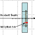
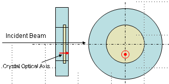
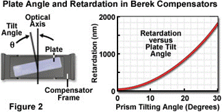
In a Berek compensator adjusted for zero retardation, the single birefringent uniaxial crystalline plate is oriented with the extraordinary optical axis perpendicular to the surface of the crystal and parallel to the microscope optical axis. Polarized light passing through the specimen encounters the compensator at normal incidence (0o) and propagates through the compensator with a velocity that is independent upon the direction of polarization. In other words, the Berek compensator acts as an ordinary isotropic material when the birefringent plate is perpendicular to the microscope optical axis, and thus, has no effect on polarized light passing through. As the compensator plate(tilt adjustment typically) is rotate with respect to the direction of incident polarized light (and microscope optical axis), the incident plane coincides with the refractive index plane of the extraordinary axis and alters the velocity of light passing through the crystal. In general, the polarized wavefront is retarded by a measurable quantity that is dependent upon the angle of tilt and the wavelength of illumination. Simultaneously, light polarized perpendicular to the incident plane continues to propagate through the compensator plate along the ordinary axis and with a velocity that remains independent upon the tilt angle. As a net result, polarized light exiting the specimen and passing through a tilted Berek compensator is retarded by an additional amount by the compensator and accumulates a relative phase shift (dependent upon the tilt angle), which can be measured with the device. The degree of optical path difference introduced by a Berek compensator is determined by the thickness of the birefringent plate, the wavelength of illumination, the refractive index difference between the ordinary and extraordinary axes of the compensator crystal, and the tilt angle. Most manufacturers compound all of these quantities into a constant that is utilized to calibrate the retardation vernier scale. |


